Introduction
Wind turbines are a great source of power, but they are also one of the most inefficient sources of energy. The challenge for engineers is to design blades that can generate enough electricity with as little wasted motion as possible. Here’s what you need to know about wind turbine blade design:
1. Wind turbine blade design basics
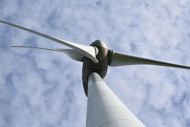
Wind turbine blades are the most important part of a wind turbine. They convert the kinetic energy of wind into mechanical energy, which is then used to turn a generator and generate electricity.
Wind turbines use three types of blades:
- Fixed-wing (aero) rotors; these rotate around their own axis, but they remain stationary relative to their centerline. They can be used in both horizontal and vertical orientations and will generate power when they are rotating at high speeds with minimal torque losses due to inertia forces acting on them (e.g., drag). Fixed-wing rotors are typically made out of composite materials such as fiberglass or carbon fiber because they offer better performance than metal ones at higher temperatures or pressures because these materials can withstand high temperatures without breaking down over time while still maintaining structural integrity when needed most—in other words: no bending!
2. Wind turbine blade design objectives
Wind turbine blade design is an important part of the overall wind power system. The objective of this section is to help you understand how wind turbine blades are designed, why they are designed that way, and how you can optimize their performance for improved efficiency and cost-effectiveness in your project.
Wind turbine blades are usually manufactured from composite materials such as graphite or carbon fiber reinforced plastic (CFRP). These materials have excellent strength-to-weight ratios which make them ideal for use in high speed applications like aircraft engines or aerospace vehicles where weight is critical but strength isn’t always required at great speeds. By using these types of materials with low density values along with other design features such as aerodynamic shape optimization we can achieve better performance than traditional steel based products without sacrificing safety measures needed during operation such as fatigue life prediction models based on analysis done prior to construction start dates when designing prototypes etc..
3. Basic aerodynamic design considerations for wind turbine blades
The basic aerodynamic design considerations for wind turbine blades are:
- Blade element momentum theory - this theory was developed in the late 1800s, and it is based on the idea that a moving body has both velocity (the speed at which it is going) and acceleration (how quickly it's moving). Therefore, if you add up all these factors—velocity and acceleration—you'll get an overall value called "momentum." Momentum is proportional to mass times velocity squared; therefore, if you increase one factor but keep another constant, then your total momentum will increase by less than proportionally.
- Aerodynamic loading - this refers to how much force acts upon your blade during operation. This includes forces from wind blowing against its surface as well as from other sources such as air turbulence caused by other objects flying through space nearby your turbine's spinning blades.* Aerodynamic design considerationsinclude factors such as airflow and its effect on the blade's shape. The greater the air pressure difference between the top and bottom of your blade, the faster it will spin—and thus generate more power from any given wind speed.
4. Aerodynamic loads on the wind turbine blade
The aerodynamic loads on the wind turbine blade are due to drag, lift and moments. Drag is a result of the aerodynamic forces acting on the blade; lift is a result of these same forces acting on the blade. Moments are associated with internal stress in an airfoil or wing structure and can be caused by multiple factors such as temperature differences between sections or localized areas within a section (e.g., near tip).
5. Blade element momentum theory
The blade element momentum theory is a method for calculating the forces on a blade. It was developed in 1968 and has been used to calculate the aerodynamic forces on wind turbines, as well as other rotating machinery.
The main elements of this theory are:
- The coefficient of airfoil drag (CABD) - This is an expression that describes how much energy is needed to move your airplane through air at different speeds. For example, if you're flying at 250 mph and there's no wind resistance, then CABD will be 0 because there's no need for additional power from your engine because it doesn't have any work to do! However if you were flying at 300 mph with moderate winds blowing against your wings then CABD would be much higher than this value due to increased drag caused by turbulence around them; this same principle applies here too: If there isn't enough lift being generated from each wingtip then some more power will need creating by adding things like elevators etcetera...
6. Other aerodynamic considerations
- Other aerodynamic considerations
The shape, size, and twist of a wind turbine blade can have a significant effect on its efficiency. A design that produces the most power with the least amount of drag will be more efficient than one that does not optimize these factors. For example, if you were designing an aircraft wing for flight at high speeds or high altitudes (elevation), you would want your wing to have as much lift as possible while still being able to produce enough thrust for takeoff and landing maneuvers (which require less lift). In this case, increasing your wing's aspect ratio would help you achieve these goals—that is, if you wanted your aircraft to fly faster or higher than other airplanes currently in use today!
Blade materials are another important factor when determining how well a turbine will perform under different conditions; however there are many other factors besides material selection which affect performance so it’s best not just focus on one thing alone but instead look at all aspects at once so as not get caught up doing things incorrectly later down line process .
7. Aerodynamic optimization techniques
- Aerodynamic optimization techniques
Aerodynamic optimization techniques can be used to adjust the shape of blades, including:
- Wind tunnel testing - This method involves testing various shapes and aerodynamically optimized configurations in a wind tunnel, using computer software to predict their performance. The results are then compared against actual performance on the field.
- Computational fluid dynamics (CFD) - This is a more advanced method that uses mathematical equations and simulations based on real world data to predict how an aircraft will behave in flight based on its wing design and thrust characteristics.
Conclusion
Through the analysis of these turbine blade designs, we have seen that they are capable of providing high power outputs while at the same time reducing costs by optimizing aerodynamic properties. This provides a great opportunity for manufacturers to develop new designs with improved efficiency and performance characteristics.